|
Comments
Manual download
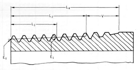
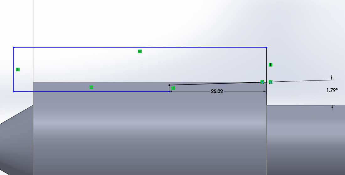
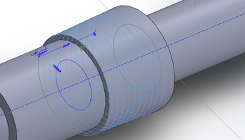
How to make nPT in Solidworks (American standard taper pipe threads size nPT chart attached)3/13/2015 National Pipe Thread Taper (NPT) is a U.S. standard for tapered threads used on threaded pipes and fittings. download:Make NPT in solidworks1. Determine the NPT thread size. 2. Find out the outside diameter of pipe according to the table. Draw a cylinder with that diameter. For example, for a NPT size of 1, the outside diameter of pipe is 1.315 inches = 33.4 mm. 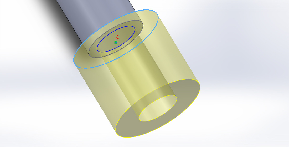 3. The taper rate for all NPT threads is 1 in 16 (3⁄4 inch per foot or 62.5 millimeters per meter) measured by the change of diameter (of the pipe thread) over distance. The angle between the taper and the center axis of the pipe is tan−1(1⁄32) = 1.7899° = 1° 47′ 24″. Be careful, it is not tan-1(1/16) here! Create the taper on the cylinder. 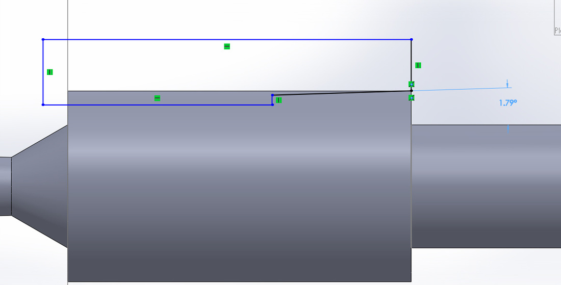 Revolved cut. 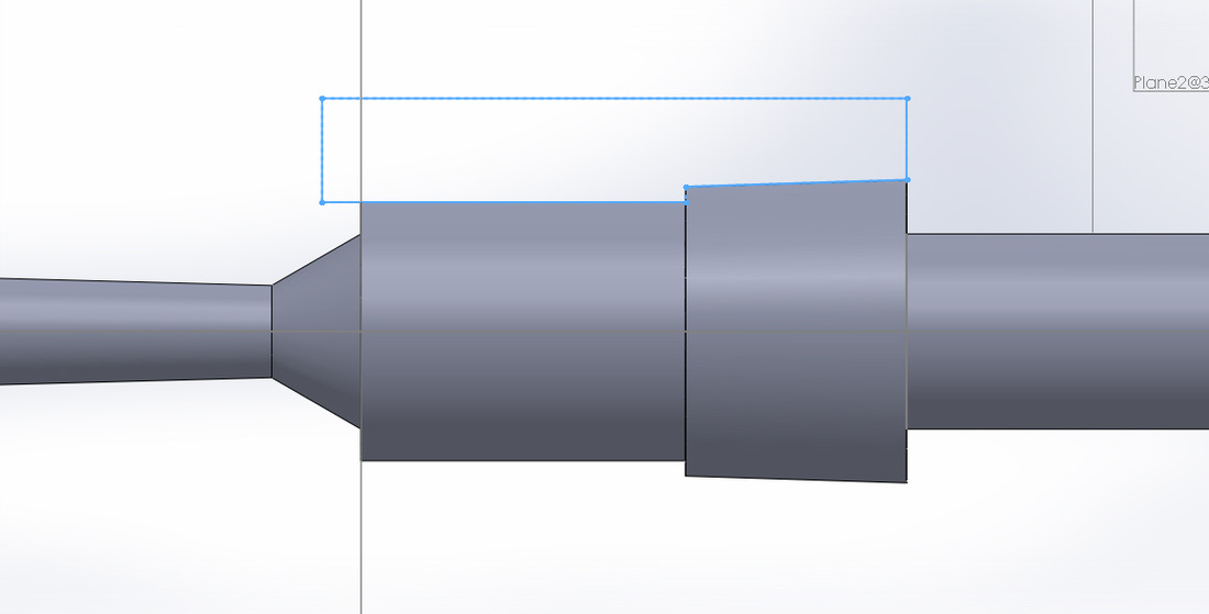 4. The basic effective length of the external taper thread, L2, includes two usable threads with slightly imperfect crests located against the the vanish threads. The length, L1, is the normal engagement between external and internal taper threads when screwed together hand tight. According to the table, for size 1, the effective thread length L2 should be 0.683 inches = 17.3482 mm and the vanish thread length V should be 0.302 inches = 7.6708 mm. Total length L4 = 0.985 inches = 25.02 mm.
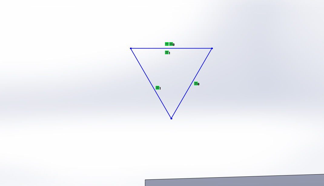
5. Create cutting profile. Draw a equilateral triangle. Find out the Pitch Diameter At Beginning of External Thread E0. This is the revolving diameter of the midpoint of the triangle at the beginning of the thread. Select the midpoint of one edge of the triangle. Set the distance between this point and the centerline according to E0. For NPT size of 1, E0 = 1.2136 inches = 30.825 mm.
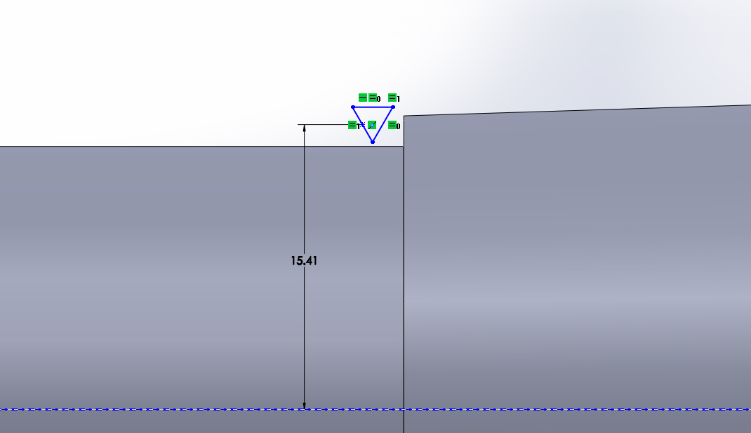
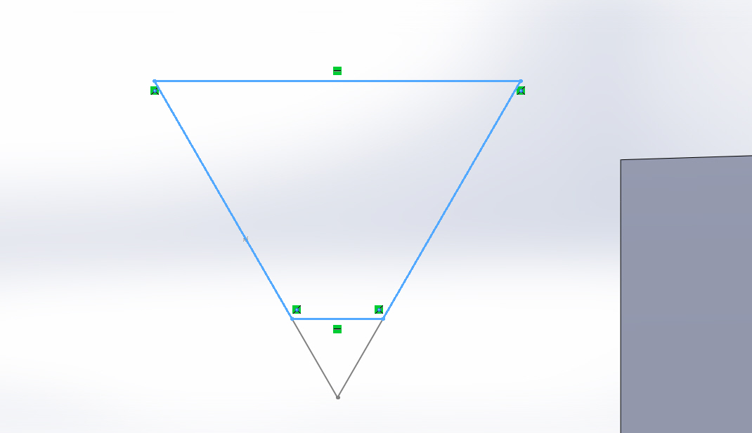
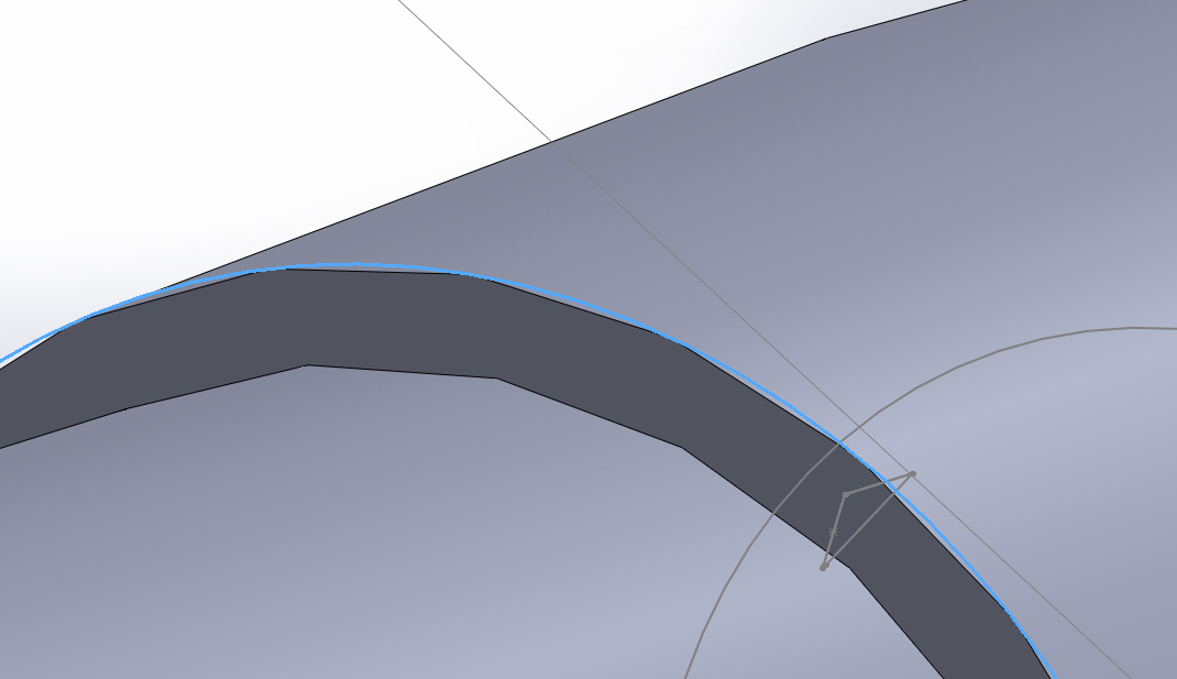
Instead of being a triangle, the cutter actually should look like which is highlighted with blue below. Its crest is truncated. Truncation crest or root for NPT 1 should be in the range of 0.0029 to 0.0063 inches (0.07366 mm to 0.16002 mm). The pitch of thread, which is the edge length of the triangle, should be 0.08696 inches = 2.209 mm.
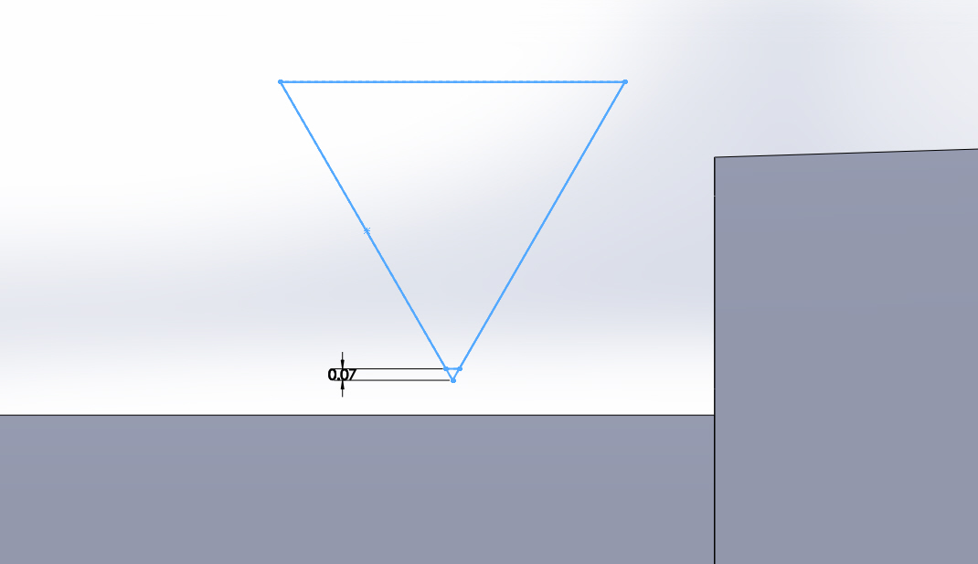
Shift the upper-right corner of the triangle to coincide with the beginning contour of the taper. 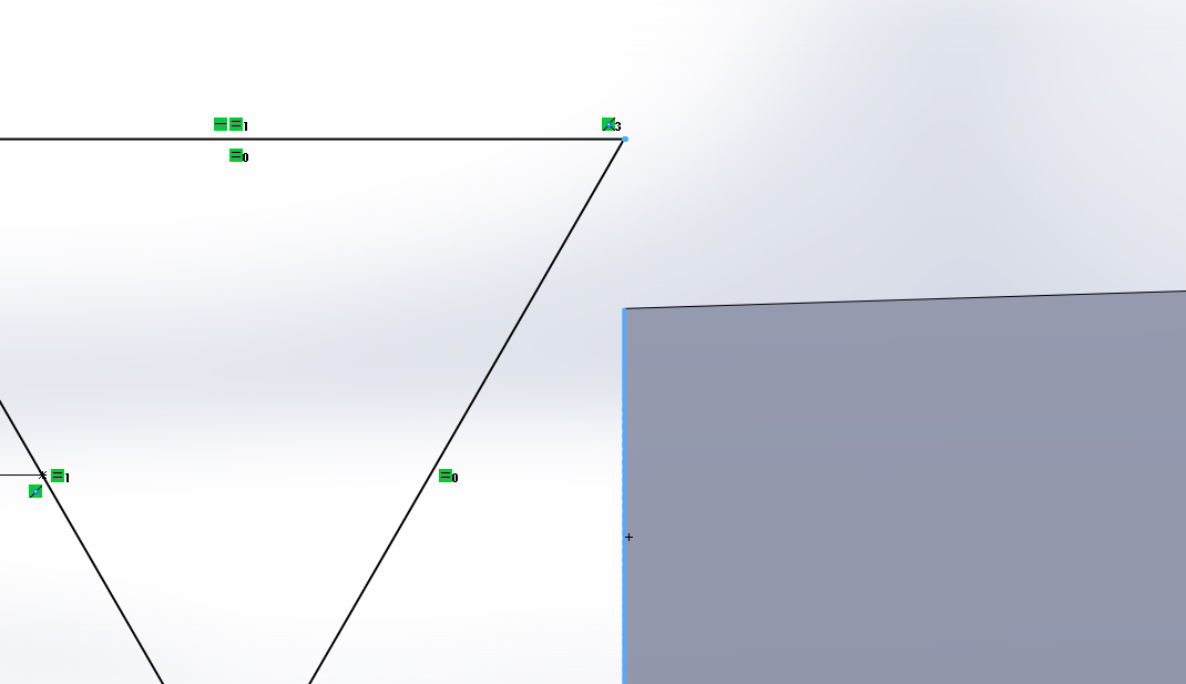 6. Create the helix contour to cut the threads, tapered outward 1.7899°. Sketch, convert the outline of the taper surface to sketch segment. Create the helix. Constant pitch equals 2.209 mm, clockwise, taper helix 1.7899° outward.
7. Sweep cut and create the thread. 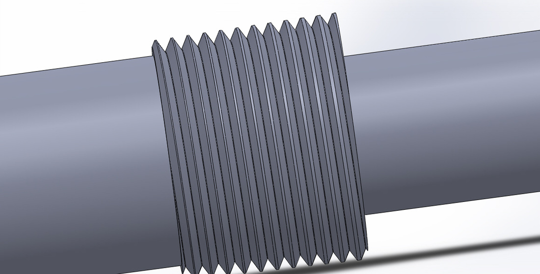 8. Further improvement. 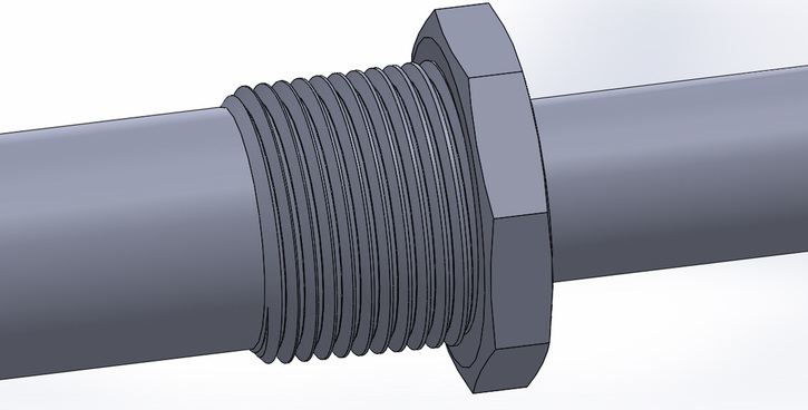
Overview
The basic function provided by EES is the solution of a set of algebraic equations. EES can also solve differential equations, equations with complex variables, do optimization, provide linear and non-linear regression, generate publication-quality plots, simplify uncertainty analyses and provide animations. EES allows the user to enter his or her own functional relationships in three ways. First, a facility for entering and interpolating tabular data is provided so that tabular data can be directly used in the solution of the equation set. Second, the EES language supports user-written Functions and Procedures similar to those in Pascal and FORTRAN. EES also provides support for user-written routines, which are self-contained EES programs that can be accessed by other EES programs. The Functions, Procedures, Subprograms and Modules can be saved as library files which are automatically read in when EES is started. Third, external functions and procedures, written in a high-level language such as Pascal, C or FORTRAN, can be dynamically-linked into EES using the dynamic link library capability incorporated into the Windows operating system. These three methods of adding functional relationships provide very powerful means of extending the capabilities of EES. Interesting practical problems that may have implicit solutions, such as those involving both thermodynamic and heat transfer considerations, are often not assigned because of their mathematical complexity. EES allows the user to concentrate more on design by freeing him or her from mundane chores. EES is particularly useful for design problems in which the effects of one or more parameters need to be determined. A new user should read Chapter 1 which illustrates the solution of a simple problem from start to finish. Chapter 2 provides specific information on the various functions and controls in each of the EES windows. The animation capabilities provided in the Diagram window are described in this chapter. Chapter 3 is a reference section that provides detailed information for each menu command. Chapter 4 describes the built-in mathematical and thermophysical property functions and the use of the Lookup Table for entering tabular data. Chapter 5 provides instructions for writing EES Functions, Procedures, Subprograms and Modules and saving them in Library files. Chapter 6 describes how external functions and procedures, written as Windows dynamic-link library (DLL) routines, can be integrated with EES. Chapter 7 describes a number of advanced features in EES such as the use of string, complex and array variables, the solution of simultaneous differential and algebraic equations, and property plots. The use of directives and macros is also explained. Appendix A contains a short list of suggestions. Appendix B describes the numerical methods used by EES. Appendix C shows how additional property data may be incorporated into EES.
Ejectors for the oil and gas industry:
Ejectors for the nuclear industry:
The boundary layer form of the Navier-Stokes equations and their treatments
Ideal gas thermodynamic properties in Chemkin format
Simple equilibrium with multiple reactions
Convergence to most probable macrostate
Spectroscopy primer
Atomic spectroscopy (NIST)
Atomic spectra term symbol and Hunds rules
Atomic term symbols
Term symbol
Quantum mechanics and spectroscopy
Ideal diatomic gas (Table of molecular constants for several diatomic molecules included)
Burcat thermo data file
Courtesy to Professor Nick Glumac
Course website: http://glumac.mechse.illinois.edu/me404/INDEX.html Search engine optimization starter guide (English)
Search engine optimization starter guide (Chinese)
|
Jingwei ZhuPh.D. candidate in the Department of Mechanical Science and Engineering at the University of Illinois at Urbana-Champaign. 
Categories
All
Archives
October 2018
|
||||||||||||||||||||||||||||||||||||||||||||||

|
|
 RSS Feed
